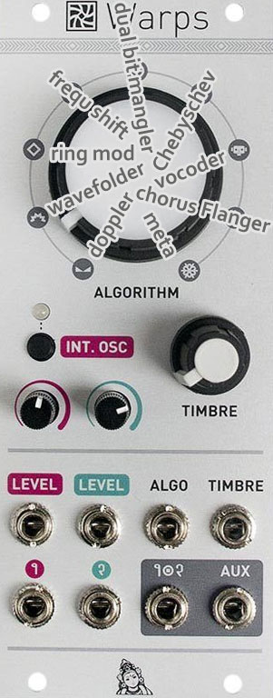
(→Parasite Firmware) |
(→Parasite Firmware) |
||
| Ligne 52 : | Ligne 52 : | ||
Red: ping-pong delay. Channel 1's feedback goes into Channel 2, and conversely. Lovely in stereo.<br/> | Red: ping-pong delay. Channel 1's feedback goes into Channel 2, and conversely. Lovely in stereo.<br/> | ||
*'''9.Meta-mode (the stock firmware's main function)''' | *'''9.Meta-mode (the stock firmware's main function)''' | ||
| + | |||
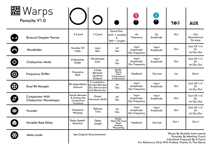
| + | [[Fichier:Warps-cheat-sheet.jpeg]] | ||
==Easter egg in the stock firmware== | ==Easter egg in the stock firmware== | ||
Version actuelle en date du 16 mai 2017 à 06:15
Mutable Instruments Warps[modifier]
Parasite Firmware[modifier]
https://mqtthiqs.github.io/parasites/warps.html
- 1.Binaural Doppler panner
the Big knob sets x coordinate of the source.
the Small knob sets y coordinate of the source.
the Tiny pots control a built-in LFO modulating the source's position on a circle around the center (technically there are two LFOs in quadrature, modulating respectively x and y). The first is its frequency, the second is its amplitude.
the Two outputs should be used as a stereo pair, obviously.
Input 1 is one sound source; Input 2 is another source that is placed symmetrically to Input 1 on the other side of the head's axis.
The state of the button determines the size of the space: from a tiny space (LED unlit), where the Doppler effect and the delay and attenuation of distant sound is minimal, to a huge one (LED red).
- 2.Wavefolder
Big knob: amount of folds
Small knob: input bias (gives access to different and subtler timbres)
The button switches the internal oscillator; Aux outputs the mix or the internal oscillator (default behavior)
- 3.Ring modulator
Big knob crossfades between digital and analog ring-mods
Small knob: soft-clipping
The button switches the internal oscillator; Aux outputs the mix or the internal oscillator (default behavior)
- 4.Frequency shifter (the stock firmware's easter egg)
Big knob frequency shift
Small knob: crossfade between up/down outputs
Tiny pots: feedback and dry/wet
Outputs: up and down
- 5.Dual bit-mangler
Big knob input bit-degradation amount.
Small knob: cross-modulation. Morphs between dry, bitwise AND and bitwise XOR.
The button switches the internal oscillator; Aux outputs the mix or the internal oscillator (default behavior)
Note: the Aux output is also affected by the bit degradation, so you can use this feature on the two channels, in stereo.
- 6.Comparator with Chebyschev waveshaper
Big knob morphs between 8 analog-like comparison functions, starting with the mix of both inputs.
Small knob: order of the Chebyschev waveshaper. A Chebyschev waveshaper shapes the signal with Chebyschev polynomials. It has the effect of shifting harmonics non-linearly by whole octaves, and gives interesting timbres out of simple ones. Fully CCW, the sound is unaffected.
The button switches the internal oscillator; Aux outputs the mix or the internal oscillator (default behavior)
- 7.Vocoder
Big knob frequency warping
Small knob: release time
The button switches the internal oscillator; Aux outputs the mix or the internal oscillator (default behavior)
- 8.Chorus/Flanger/Slapback
This mode simulates classic effects that can be achieved with a small delay line.
the Big knob sets the delay time, from sub-audio to about 200 ms.
the Small knob sets the amount of feedback. Fully CCW, you'll have only the dry sound.
the Tiny pots control a built-in LFO modulating the delay time. The first is its frequency, the second is its amplitude.
The state of the button determines the topology of the delay:
Unlit: open feedback loop. In 1 is the input, Out the output. Aux is the feedback output and In 2 is the feedback input.
Green: dual delay. In 1/Out are one channel, In 2/Aux are another. They share the same delay time.
Orange: dual analog-modeled delay. My modest take on tape delay simulation. The feedback path goes through LP/HP filters and a light distortion; a tad of hiss is also added.
Red: ping-pong delay. Channel 1's feedback goes into Channel 2, and conversely. Lovely in stereo.
- 9.Meta-mode (the stock firmware's main function)
Easter egg in the stock firmware[modifier]
https://www.muffwiggler.com/forum/viewtopic.php?p=2063240#2063240
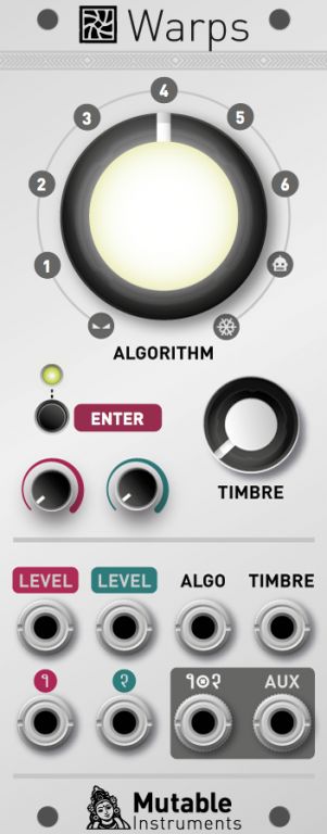
remove any inputs, put the timbre and two level knobs all the way to the left as in Olivier's image, then enter that sequence with the big knob.
1) 2
2) 4
3) 3
4) 6
5) 1
6) 5
7) Die is thrown but caught before it lands
Just dial in these numbers with the big knob and press the button after each number!
https://www.muffwiggler.com/forum/viewtopic.php?p=2063918#2063918
pichenettes Veteran Wiggler
Joined: 06 Aug 2012
Last Visit: 27 Nov 2015
[Years of Membership] [Years of Membership] [Years of Membership]
Posts: 613
Location: Paris
PostPosted: Thu Nov 26, 2015 10:40 pm Post subject: Reply with quote Add User to Ignore List Here's a little explanation about the easter egg...
With INT. OSC enabled, the module works as a frequency shifter.
ALGORITHM knob and ALGO CV input: frequency shift. No shifting at 12 o'clock, positive frequencies when turning CW, negative frequencies when turning CCW. The control curve is linear until 50 Hz then becomes exponential. The response of the ALGO CV input (which modulates shifting amount) depends on the position of the big knob - it is linear when the big knob is near its central position, and 1V/Octave-ish when the big knob is above 50 Hz or below -50Hz.
INT. OSC: carrier waveform. Available waveforms: sine, three harmonics, "random" signal created by summing 7 harmonics with random amplitudes/phases. With a low frequency shifting amount, you can think of this as the tremolo/delay/phasing modulation waveform. Another way to think about this parameter is that there will be one shifted "copy" of the input signal per harmonic of the carrier waveform.
LEVEL 1 CV/knob: feedback amount.
LEVEL 2 CV/knob: dry/wet amount.
TIMBRE: balance between the lower and upper sidebands. Both sidebands are present (ring-modulation) when the knob is at 12 o'clock.
AUDIO IN 1 & 2: two audio inputs, summed together.
AUDIO OUT 1+2 / AUX: the two audio outputs react reversely to the TIMBRE knob. For example, if TIMBRE is fully CCW, 1+2 will output the lower sideband, and AUX will output the upper sideband. Great for generating a wide stereo image!
Now what happens when you disable INT. OSC? The module becomes a kind of "quadrature cross-modulator". Mathematically, it computes the product of the analytic signals obtained from inputs 1 and 2, and another complex exponential - then the real and imaginary parts of the result are dispatched to the two outputs. This one is tricky to explain! You can think of it as frequency shifting, except that instead of dialing the shifting frequency with the big knob, you directly feed a sinewave at this frequency on input 1 to shift input 2. Obviously, feeding a waveform more complex than a sinewave on input 1 will cause multiple shifts of the signal on input 2 - creating very complex inharmonic tones! When INT. OSC is disabled, ALGORITHM controls the amount of phase shifting on the result of the modulation. You won't hear much difference when you move it very slowly - the magic happens when it is modulated.


