liste des modules Malekko Wiard 300
Sommaire
Joystick Axis Generator[modifier]
Introduction 1[modifier]
Grant: JAG introductory notes
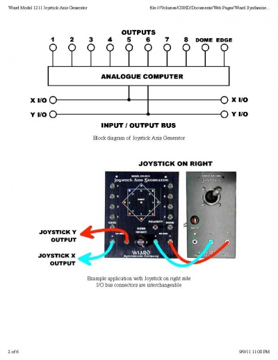
The JAG is a new module design that takes any two input voltages, and makes all the inversions and combinations available simultaneously. It is a two input, ten output folder/twister/combiner.
You could also look at it as a kind of Cartesian barberpole generator.
They original X and Y inputs are passed through to be used in the patch. Or a second unit with X and Y switched will give another 10 functions shifted by 90 degrees. The output fuctions can also be used an inputs to another JAG for really bizarre shapes.
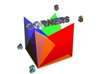
The most obvious application is for panning. The corner functions supply control for the 4 VCAs, and the edge function supplies a correction function for equal power panning. The function is used to boost the output in the middle of the pan, eliminating the power drop in the middle.
Run the other way, it is useful for Joystick controlled MIXING. For example, running 4 waveforms from a VCO to 4 VCAs allows you to mix them with a Joystick. This is also called "Vector Synthesis" since the Joystick voltages can be replaced with envelope voltages or LFOs. The 4 waveforms could also be the output of 4 different effects units or other waveform processors.
Another example is to use two envelopes as the inputs. This will produce 10 envelope "variations" that can be routed to 10 different parameters in a patch (PWM, filter sweep, filter Q, crossfading between two filters, waveshape control, envelopes times etc.).
If a Joystick is used, it gives you control of patch timbre in real time. Fun when you are running a sequence and dynamically morphing timbres. For example, the four corner or side functions can control all 4 attack, decay, sustain and release times at once. So the single Joystick can give you all possible envelope shapes mapped across the Joystick plane.
Introduction 2[modifier]
Put in the simplest terms, and staying in one coordinate system, a JAG is a phase decoder or phase remaper is a better term.
It takes X and Y input coordinates, which would normally go +/- 5 volts for example, and remaps them so that many possible combinations are available in parallel.
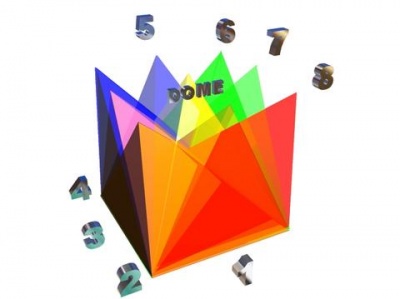
Picture a pendulum centered over the middle, as the pendulum swings in a circle, each output in turn goes high to show that pendulum is in that section of the square. We also have a function which goes high is the pendulum is sitting exactly in the middle and not moving (the "Dome" output).
Why does this exist? Well in every system you have some kind of control voltage mixer that combines two modulators and allows you to control the polarity and amplitude. This module makes all possible positive and negative inversions available simultaneously. It also allows you to do vector synthesis and quadraphonic panning.
You may have noticed the "Phase" knob on the oscillator. If you showed Saw1 vesus Saw2 on an oscilloscope set to XY mode, you would notice that each setting of the "Phase" knob will produce a little visual "dance" on the o'scope screen. If you ran them to the X and Y input input of the JAG and phase modulated them at the oscillator, the various JAG outputs will start to rotate at audio rates and harmonic cancellation and stuff.
Look, mathematics is a pain on the brain. I do it so you don't have to. The LED lights should give you all the feedback you need to apply this device.
Yes, it came out of a purely mathematical idea, but so does any VCO or any module. And the ONLY way to test the musical usefulness is to build a prototype and LISTEN to it! For each type of prototype you build based on underlying mathematical idea's one out of 10 or one out of 20 is a keeper.
I thought this was a keeper. Like any musical instrument, you get out what you put into it. You can't break it from the front so just goof around and try stuff. Your ears are the only critic. Enjoy the light show!
BTW, just for good luck, the LED colors match the Ancient Chinese Bag'ua or eight sided figure formed by the eight possible I Ching coin combinations (only blue is subed for black and orange is subed for white).
I HAVE to stop over thinking these things ;^)
Have Fun!
Introduction 3[modifier]
The JAG is a new module design that takes any two input voltages, and makes all the inversions and combinations available simultaneously. It is a two input, ten output folder/twister/combiner. It operates up to a full 20 kHz bandwidth, so you can combine audio waveforms. You could take two waveforms from the same VCO and generate 10 variations. As an effect unit, it is most like ring modulation or other non-linear mixing sound. Makes an interesting fuzz box with 10 output variations.
There is an input polarity switch which switches between a 0-10 volt inputs and +/- 5 volt inputs. Also the 8 outputs can be used to control all 4 ADSR parameters of two envelope generators simultaneously. Combining two LFOs give 10 variations for sweeping and control of parameters. Up to 8 bandpass filters can be controlled by Joystick for generating formants or comb filters (like a phase shifter constructed of individually controllable peaks or notches). You could also look at it as a kind of Cartesian barberpole generator.
The original X and Y inputs are passed through to be used in the patch. Or a second unit with X and Y switched will give another 10 functions shifted by 90 degrees. The output fuctions can also be used as inputs to another JAG for really bizarre shapes. The most obvious application is for panning. The corner functions supply control for the 4 VCAs, and the edge function supplies a correction function for equal power panning. The function is used to boost the output in the middle of the pan, eliminating the power drop in the middle. Run the other way, it is useful for Joystick controlled MIXING. For example, running 4 waveforms from a VCO to 4 VCAs allows you to mix them with a Joystick. This is also called "Vector Synthesis" since the Joystick voltages can be replaced with envelope voltages or LFOs. The 4 waveforms could also be the output of 4 different effects units or other waveform processors. Another example is to use two envelopes as the inputs. This will produce 10 envelope "variations" that can be routed to 10 different parameters in a patch (PWM, filter sweep, filter Q, crossfading between two filters, waveshape control, envelopes times etc.). If a Joystick is used, it gives you control of patch timbre in real time. Fun when you are running a sequence and dynamically morphing timbres. For example, the four corner or side functions can control all 4 attack, decay, sustain and release times at once. So the single Joystick can give you all possible envelope shapes mapped across the Joystick plane. Complicated, mysterious, yes, but I also think it will be great fun too. There are 9 LEDS on the faceplate that indicate the output voltages. A great light show, but it also gives an intuative grasp of what is happening. This experimental module produces 10 complex output voltages from two input voltages. It has 9 LEDs of every color except violet. The most obvious application is control signals for quadraphonic panning. It also provides the control signals for volume and reverberation control for location modulation. If you have worked with the Buchla reverb module, this allows you to patch up the "Recede" fuction where volume, reverb and panning are controlled automatically. Using the Borg Filters in the VCA mode also provides the high frequency roll-off with distance cue, which mimics the effect of humidity damping with acoustic signals. A less obvious application is timbre control via joystick. Since you have 10 crossfading control signals, you can route them to filter frequency, filter Q, PWM, waveshape select, filter type select and anything else. Now you can adjust 10 parameters simultaneously using a single joystick.
Question/answer[modifier]
> What is the upper frequency limit for the JAG?
The op-amps are TL074s. It should work to about 2 megahertz. IN other words you could
process video with it (what that would get you I do not know).
> Will it work at audio rates?
No problem.
> Is it all analog?
Discrete class A circuitry actually.
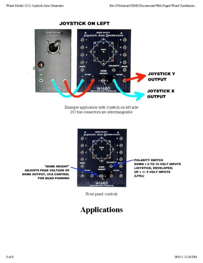
> The polarity switch switches the INPUTS only. Use in the down position for 0 - 10 volt joysticks and envelope generators.
> Use in the up position for dual LFOs that produce +/- 5 volt waveforms.
> The outputs are always 0 - 10 volts (approx.)
First off the best and easiest way to comprehend the JAG is in a demo. This is one module wherein the visual feedback from the panel LED's are the best way to comprehend the functions. If you know someone with a JAG i urge you to go borrow some time with it. (that will be LOTs more fun than reading this anyway!)
The first, important distinction, is that the JAG is NOT a joystick. It's a processor. (it can even process audio, but for sake of clarity i'm not even going there).
The X & Y jacks are INPUTs, They can certainly be connected to your A-174's but they can just as easily accept a couple of LFO's or Envelopes.
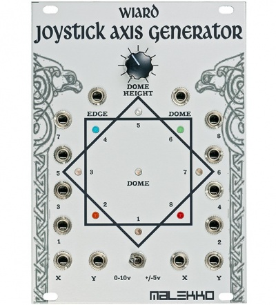
The JAG turns the TWO vectors of control at the X & Y inputs into ten INDEPENDENT output vectors, at each LED (and the two 'invisible vectors of "dome" and "edge") by comparison a conventional Joystick outputs only two INDEPENDENT vectors per module (x & y). You can mult the outputs of the A-174 (to the limit of the joystick's available drive current) but that doesn't multiply the number of INDEPENDENT vectors available.
Those are some of the essential differences. That key word i keep capitalizing is Independent vectors of control; the ability to move one CV up- while moving another down - while holding three other CVs steady- and creating a 'bump' in yet another CV.... ALL WITH ONE MOTION!
Combined with a joystick, i find the JAG can output an array of CV's that allow me to rival the level of control over an analog synth that one can exert over an acoustic instrument. Used a different way the JAG outputs enough control to allow you to 'conduct' complex 'ensembles' of multiple voices.
To compare again... with 2 joysticks you have independent mix control over 4 voices (via VCA's). with 2 JAGs you would have independent mix control over 20 voices (likewise via VCA's) The "Dome" function indicator is the Yellow LED in the middle. The "Edge" function is the inverse of dome (more or less).
BTW, the color mapping of the LEDs is inspired by one of the Chinese color mapping of the "Ba- Gua" ( https://en.wikipedia.org/wiki/Bagua ) or eight sided figure showing the eight possible outcomes of the three "I-Ching" coins. Blue was substituted for black (North). When I mentioned Feng Shui to my fellow engineer Chunning Sang, he replied "Next you'll be telling me you've seen a UFO, only my grandparents believe in that stuff!"
Both Western and Eastern Geomancy are fascinating topics however. It is amazing how much
the human belief system has changed over a short time. For example, earlier humans believed
that evil traveled in straight lines, and avoided straight lines in art and even fences. This is why
much early art contains great complexity (such as celtic knots). It was believed that these highly
tangeld lines would prevent the entrance of evil. The idea was so universal that there is a specific
word for it, "apotropaic" meaning "intended to ward off evil or bad influences". Rest assured, all
Wiard product produce waveforms of apotropaic complexity, and can only be good for you! I
am only kidding around, so don't send the guys from the Funny Farm.
Pictures[modifier]
| | |
| | |
| | | |
| | |
Yohda,du forum synhe-modulaire.com[modifier]
(à vérifier)
Je m'étais amusé il y a quelques temps à reproduire les mêmes fonctions avec des modules plus classiques :
En mixant/inversant les sorties X/Y d'un Joystick :
- 1 = inverse Y
- 2 = (inverse X + inverse Y)/2
- 3 = inverse X
- 4 = (inverse X + Y)/2
- 5 = Y
- 6 = (X + Y)/2
- 7 = X
- 8 = (X + inverse Y)/2
- Dôme = 10V + (inverse rectified X + inverse rectified Y)/2
- Edge = (rectified X + rectified Y)/2
Et voilà ! Je ne suis pas sûr que le JAG fonctionne de cette manière : je ne l'ai jamais testé, mais en théorie les résultats devraient être identiques.
Applications[modifier]
panning[modifier]
There is difference between quad panning and location modulation.
Location modulation has to contain all of the Doppler shifting, frequency rolloff with distance and, reverberation clues that the ear needs to find location modulation believable.
Doppler shifting can be simulated by using the frequency inputs of the oscillator. Up-shift as object approaches, no shift when object is still, down shift when object recedes. The "Dome" function can be patched for that. Also used as a function of overall volume also.
High frequencies roll off with distance due to the friction created by humidity in the air. With the Borg in VCA mode, these frequency and amplitude characteristics with humidity are simulated.
The further away an object gets, the more overall reverberation it has, the "EDGE" function can be used to control reverberation wet/dry mix so reverberation in minimum in the middle and increases as you recede from center position.
The JAG is actually a Cartesian to Polar coordinate system converter. That is mathematically impossible, but I didn't know any better so I just did it.
In each case the polar output of the X,Y address appears as individual function. So if we want a function where the output is at max when X and Y are at 10 volts. That is position 6.
Now morphing or panning is almost perfect with linear VCA (OUT2 = Y * -coef, OUT4 = Y * +coeff, coeff = Y axis position.)
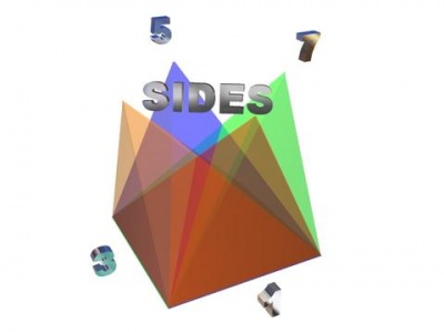
If all you have is exponential VCA's, you will need to add a 5th VCA with an equal power correction function. That is what functions 1, 3, 5, 7 are for and their algebraic summation "EDGE".
Basically use the 5th VCA and the equal power correction curves to fix the apparent drop in power in the middle of the sweep caused by the exponential VCAs.
Logic[modifier]
The JAG can work as a logic module--just patch two gates into the X/Y and you get: 6: AND 2: NOR The other outputs give some funky/attenuated variations as well , you can get different logic from the jag outputs by attenuating the inputs or inverting the outputs.
Logic Switch[modifier]
- Use the JAG as a switch for logic signals: set the JAG for unipolar operation, send a clock signal (or any other logic signal, it doesn't have to be a steady clock) to the "X" input. Now we'd like to route this clock to one of two different destinations, and we'd like the choice of which one to depend on the state (high or low) of another logic signal, for instance coming from a manual gate module (or another clock, ...). For this, connect the manual gate to the "Y" input of the JAG. Use outputs "8" and "6". When the manual gate output is high, the original clock signal will appear at output 6, when low, you'll find it at output 8. (Note that how good this works might depend on the levels of the gate signals you are feeding the JAG. There are hardly any standards in Eurorack, so this patch may not always give the expected result.) In fact, the same patch will allow you to use the JAG as a switch for other signals as well, for instance an LFO: simply plug that into the X input instead of a clock. However, you should definitely not expect exact copies of your LFO signal to appear at the outputs. While the JAG has its uses as a switch for non-logic signals, you shouldn't expect your 1V/Oct melodies to come back out of it in tune!
tips[modifier]
http://www.muffwiggler.com/forum/viewtopic.php?t=12101
the JAG can work as a logic module--just patch two gates into the X/Y and you get:
6: AND 2: NOR
the other outputs give some funky/attenuated variations as well you can get different logic from the jag outputs by attenuating the inputs or inverting the outputs. (i always thought to do this but never patched it up until tonight, so i thought id jot it down)
One tip is to take the Noisering 1 and 2 outputs and run them into X and Y in on the JAG 0-10v range. Now you have 10 stepped random voltage sources controlled by the "Rate" clock. You can run the clock itself into an envelope generator. Now run the "Dome" output into a quantizer and then the 1v/oct input of a VCO. "Dome Height" controls melody range. Patch up your classic VCO-VCF-VCA and use all the random voltages to control stuff. Sequencer like but with much greater tambral variation.
Technical[modifier]
jumpers[modifier]
the odd and even jumpers have to do with the Edge output
Details[modifier]
The Joystick Axis Generator is 18hp wide, 25mm deep, and consumes around 80mA power.
note sur le selecteur[modifier]
sur le module de malekko, le switch 0-10v +/-5v est inversé ! erreur de conception de la façade.
The input level can be switched to either 0-10 Volts (unipolar), or -5/+5 Volts (Bipolar). NOTE: The Malekko/Wiard JAG labeling of the polarity switch is reversed; just flip the switch and it will be easy to tell when you have the right setting for your modulation source.
more tips on JAG[modifier]
check the Wiard_300_tips_and_tricks page
